Mesh Hierarchy
In GEOS, the mesh structure consists of a hierarchy of classes intended to encapsulate data and functionality for each topological type. Each class in the mesh hierarchy represents a distinct topological object, such as a nodes, edges, faces, elements, etc. The mesh data structure is illustrated in an object instantiation hierarchy. The object instantiation hierarchy differs from a “class hierarchy” in that it shows how instantiations of each class relate to each other in the data hierarchy rather than how each class type relates to each other in an inheritance diagram.

Fig. 98 Object instances describing the mesh domain. Cardinalities and relationships are indicated.
To illustrate the mesh hierarchy, we propose to present it along with a model with two regions (Top and Bottom) (Fig. 99).
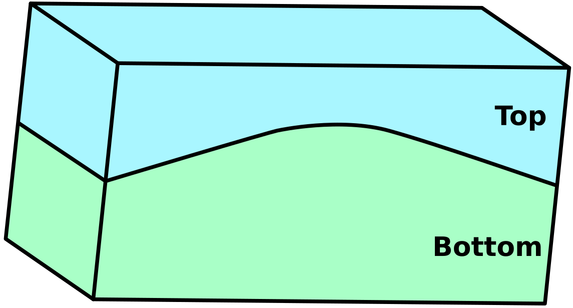
Fig. 99 Example of a model with two regions
DomainPartition
In Fig. 98 the top level object DomainPartition represents
a partition of the decomposed physical domain.
At this time there is a unique DomainPartition for every MPI rank.
Note
Hypothetically,
there may be more than one DomainPartition in cases where the ranks are overloaded.
Currently GEOS does not support overloading multiple DomainPartition’s onto a rank, although
this may be a future option if its use is properly motivated.
For instance, the model presented as example can be split into two different domains (Fig. 100).
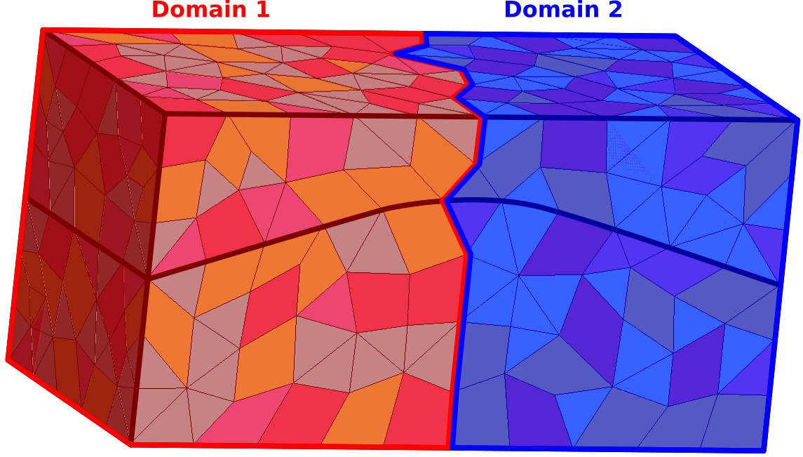
Fig. 100 Mesh partioned in two DomainPartition
MeshBody
The MeshBody represents a topologically distinct mesh body.
For instance if a simulation of two separate spheres was required, then one option would be to have
both spheres as part of a single mesh body, while another option would be to have each sphere be
a individual body.
Note
While not currently utilized in GEOS, the intent is to have the ability to handle the bodies
in a multi-body mesh on an individual basis.
For instance, when conducting high resolution crush simulations of granular materials (i.e. sand),
it may be advantagous to represent each particle as a MeshBody.
MeshLevel
The MeshLevel is intended to facilitate the representation of a multi-level discretization of a MeshBody.
Note
In current practice, the code utilizes a single MeshLevel until such time as we
implement a proper multi-level mesh capability.
The MeshLevel contains the main components that compose a discretized mesh in GEOS.
Topological Mesh Objects
Each of the “Manager” objects are responsible for holding child objects, data, and providing functionality
specific to a single topological object.
Each topological object that is used to define a discretized mesh has a “Manager” to allow for simple
traversal over the hierarchy, and to provide modular access to data.
As such, the NodeManager manages data for the “nodes”, the EdgeManager manages data for the edges, the FaceManager holds data for the faces and the ElementRegionManager manages
the physical groups within the MeshLevel ( regions, fractures, wells etc…).
Additionally each manager contains index maps to the other types objects that are connected to the
objects in that manager.
For instance, the FaceManager contains a downward pointing map that gives the nodes that comprise each
face in the mesh.
Similarly the FaceManager contains an upward pointing map that gives the elements that are connected
to a face.
ElementRegionManager
The element data structure is significantly more complicated than the other Managers.
While the other managers are “flat” across the MeshLevel, the element data structure seeks to provide
a hierarchy in order to define groupings of the physical problem, as well as collecting discretization of
similar topology.
At the top of the element branch of the hierarchy is the ElementRegionManager.
The ElementRegionManager holds a collection of instantiations of ElementRegionBase derived
classes.
ElementRegion
Conceptually the ElementRegion are used to defined regions of the problem domain where a
PhysicsSolver will be applied.
The
CellElementRegionis related to all the polyhedraThe
FaceElementRegionis related to all the faces that have physical meaning in the domain, such as fractures and faults. This object should not be mistaken with theFaceManager. TheFaceManagerhandles all the faces of the mesh, not only the faces of interest.The
WellElementRegionis related to the well geometry.
An ElementRegion also has a list of materials allocated at each quadrature point across the entire
region.
One example of the utility of the ElementRegion is the case of the simulation of the mechanics
and flow within subsurface reservoir with an overburden.
We could choose to have two ElementRegion, one being the reservoir, and one for the
overburden.
The mechanics solver would be applied to the entire problem, while the flow problem would be applied only
to the reservoir region.
Each ElementRegion holds some number of ElementSubRegion.
The ElementSubRegion is meant to hold all the element topologies present in an ElementSubRegion
in their own groups.
For instance, for a CellElementRegion, there may be one CellElementSubRegion for all
tetrahedra, one for all hexahedra, one for all wedges and one for all the pyramids (Fig. 101).
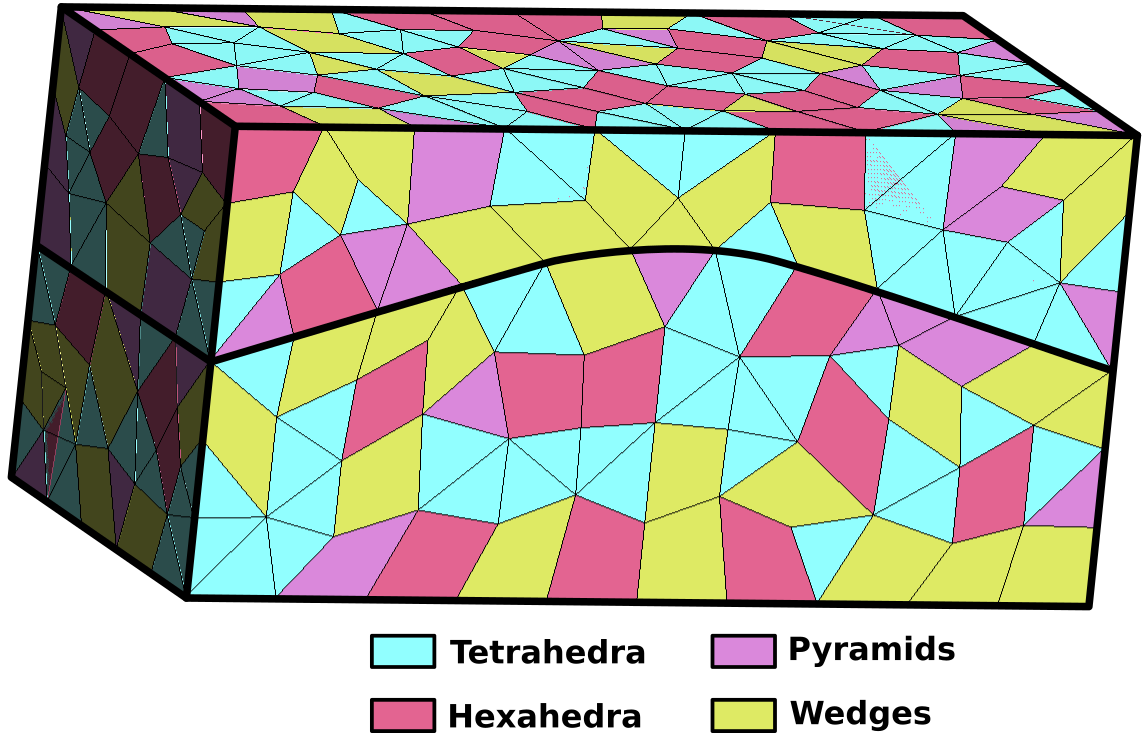
Fig. 101 Model meshed with different cell types
Now that all the classes of the mesh hierarchy has been described, we propose to adapt the diagram presented in Fig. 98 to match with the example presented in Fig. 99.
Direct links to some useful class documentation: