Tutorial 4: Boundary Conditions and Time-Dependent Functions
Context
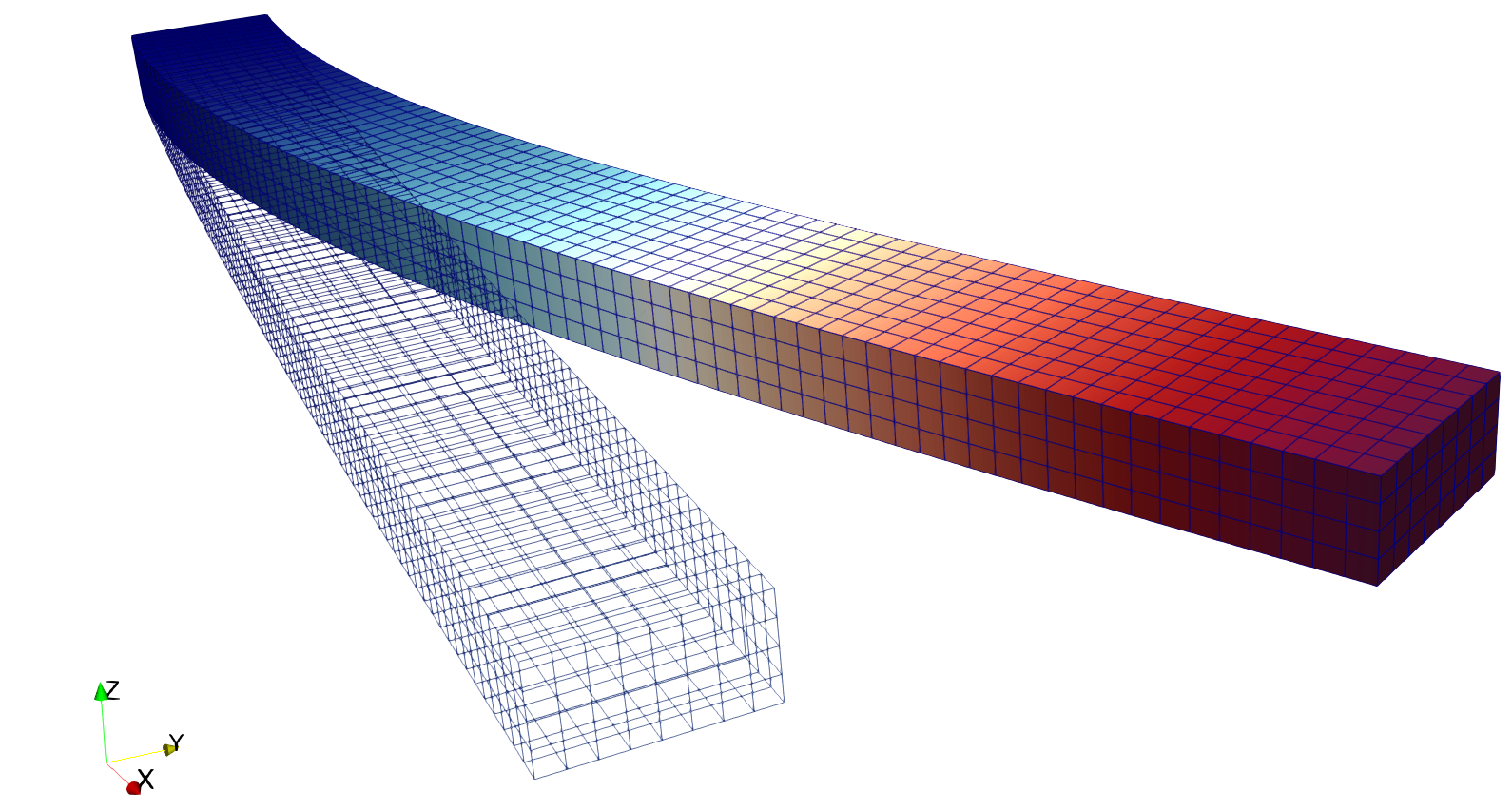
In this tutorial, we use a small strain linear elastic based solid mechanics solver (see Solid Mechanics Solver) from GEOS to solve for the bending problem of a three-dimensional cantilever beam. The beam is fixed at one end, and subjects to a traction force pointing to the y-positive direction on the other end. The beam is deformed in the x-y plane.
Objectives
At the end of this tutorial, you will know:
how to use the solid mechanics solver to solve a quasistatic problem,
how to set up displacement boundary condition at element nodes,
how to set up traction boundary condition on element surfaces,
how to use a table function to control time-dependent loading.
Input file
This tutorial uses no external input files and everything required is contained within a single GEOS input file. The xml input file for this test case is located at:
inputFiles/solidMechanics/beamBending_base.xml
inputFiles/solidMechanics/beamBending_benchmark.xml
Discretized computational domain
The following mesh is used in this tutorial:

This mesh contains 80 x 8 x 4 eight-node brick elements in the x, y and z directions, respectively.
Here, the InternalMesh
is used to generate a structured three-dimensional mesh with C3D8 as
the elementTypes. This mesh is defined as a cell block with the name
cb1.
  <Mesh>
    <InternalMesh
      name="mesh1"
      elementTypes="{ C3D8 }"
      xCoords="{ 0, 80 }"
      yCoords="{ 0, 8 }"
      zCoords="{ 0, 4 }"
      nx="{ 160 }"
      ny="{ 16 }"
      nz="{ 8 }"
      cellBlockNames="{ cb1 }"/>
  </Mesh>
Gravity
The gravity is turned off explicitly at the beginning of the input file:
  <Solvers
    gravityVector="{ 0.0, 0.0, 0.0 }">
Solid mechanics solver
The solid mechanics solver is based on the small strain Lagrangian finite element formulation.
The problem is run as QuasiStatic without considering the beam inertial. The computational
domain is discretized by FE1,
which is defined in the NumericalMethods block. The material is designated as
shale, whose properties are defined in the
Constitutive block.
    <SolidMechanicsLagrangianFEM
      name="lagsolve"
      discretization="FE1"
      targetRegions="{ Region2 }"
      logLevel="1">
Finite element discretization
The computational domain is discretized by C3D8 elements with the first order interpolation
functions at each direction in the parent domain. The 2 x 2 x 2 Gauss quadrature rule is adopted to be
compatible with the first order interpolation functions.
  <NumericalMethods>
    <FiniteElements>
      <FiniteElementSpace
        name="FE1"
        order="1"/>
    </FiniteElements>
  </NumericalMethods>
Constitutive model
Recall that in the SolidMechanicsLagrangianFEM block,
shale is designated as the material in the computational domain. Here, the material
is defined as linear isotropic.
    <ElasticIsotropic
      name="shale"
      defaultDensity="2700"
      defaultBulkModulus="5.5556e9"
      defaultShearModulus="4.16667e9"/>
Boundary conditions
As aforementioned, the beam is fixed on one end, and subjects to surface traction on
the other end. These boundary conditions are set up through the FieldSpecifications block.
Here, nodeManager and
faceManager
in the objectPath indicate that the boundary conditions are applied to the element nodes and faces, respectively.
Component 0, 1, and 2 refer to the x, y, and z direction, respectively. And the non-zero values given by
Scale indicate the magnitude of the loading. Some shorthands, such as
xneg and xpos, are used as the locations where the boundary conditions are applied in the computational domain.
For instance, xneg means the portion of the computational domain located at the left-most in the x-axis, while
xpos refers to the portion located at the right-most area in the x-axis. Similar shorthands include ypos, yneg,
zpos, and zneg. Particularly, the time-dependent loading applied at the beam tip is defined through a function with
the name timeFunction.
  <FieldSpecifications>
    <FieldSpecification
      name="xnegconstraint"
      objectPath="nodeManager"
      fieldName="totalDisplacement"
      component="0"
      scale="0.0"
      setNames="{ xneg }"/>

    <FieldSpecification
      name="yconstraint"
      objectPath="nodeManager"
      fieldName="totalDisplacement"
      component="1"
      scale="0.0"
      setNames="{ xneg }"/>

    <FieldSpecification
      name="zconstraint"
      objectPath="nodeManager"
      fieldName="totalDisplacement"
      component="2"
      scale="0.0"
      setNames="{ zneg, zpos }"/>

    <Traction
      name="xposconstraint"
      objectPath="faceManager"
      scale="1.0e6"
      direction="{ 0, 1, 0 }"
      functionName="timeFunction"
      setNames="{ xpos }"/>
  </FieldSpecifications>
Table function
A table function is used to define the time-dependent loading at the beam tip. The coordinates and values form a time-magnitude
pair for the loading time history. In this case, the loading magnitude increases linearly as the time evolves.
  <Functions>
    <TableFunction
      name="timeFunction"
      inputVarNames="{ time }"
      coordinates="{ 0.0, 10.0 }"
      values="{ 0.0, 10.0 }"/>
  </Functions>
Execution
Finally, the execution of the simulation is set up in the Events block, where
target points to the solid mechanics solver defined in the Solvers block, and
the time increment forceDt is set as 1.0s.
    <PeriodicEvent
      name="solverApplications"
      forceDt="1.0"
      target="/Solvers/lagsolve"/>
Result
The deformed beam is shown as following (notice that the displacement is visually magnified):

To go further
Feedback on this tutorial
This concludes the solid mechanics for small-strain linear elasticity tutorial. For any feedback on this tutorial, please submit a GitHub issue on the project’s GitHub page.
For more details
More on meshes, please see Meshes.
More on events, please see Event Management.