Cased Elastic Wellbore Problem
Problem description
This example uses the solid mechanics solver to handle a cased wellbore problem subjected to a pressure test. The completed wellbore is composed of a steel casing, a cement sheath and rock formation. Isotropic linear elastic behavior is assumed for all the three materials. No separation is allowed for the casing-cement and cement-rock contact interfaces.
Analytical results of the radial and hoop stresses,  and
and  , in casing, cement sheath and rock are expressed as (Hervé and Zaoui, 1995) :


where  and
and  are the Lamé moduli,
  is the radial coordinate,
  and
and  are piecewise constants that are obtained by solving the boundary and interface conditions, as detailed in the post-processing script.
Input file
This benchmark example uses no external input files and everything required is contained within two GEOS xml files that are located at:
inputFiles/wellbore/CasedElasticWellbore_base.xml
and
inputFiles/wellbore/CasedElasticWellbore_benchmark.xml
The corresponding integrated test is
inputFiles/wellbore/CasedElasticWellbore_smoke.xml
In this example, we would focus our attention on the Solvers, Mesh and Constitutive tags.
Solid mechanics solver
As fluid flow is not considered, only the solid mechanics SolidMechanicsLagrangianFEM solver is required for solving this linear elastic problem. In this solver, the three regions and three materials associated to casing, cement sheath and rock are respectively defined by targetRegions and solidMaterialNames.
    <SolidMechanicsLagrangianFEM
      name="lagsolve"
      discretization="FE1"
      logLevel="0"
      targetRegions="{ casing, cement, rock }">
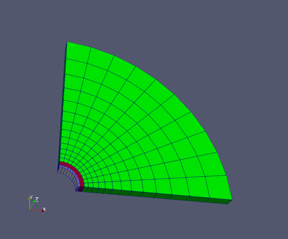
Cased wellbore mesh
The internal wellbore mesh generator InternalWellbore is employed to create the mesh of this wellbore problem. The radii of the casing cylinder, the cement sheath cylinder and the far-field boundary of the surrounding rock formation are defined by a vector radius. In the tangent direction, theta angle is specified from 0 to 360 degree for a full geometry of the domain. Note that a half or a quarter of the domain can be defined by a theta angle from 0 to 180 or 90 degree, respectively. The trajectory of the well is defined by trajectory, which is vertical in this case. The autoSpaceRadialElems parameters allow optimally increasing the element size from local zone around the wellbore to the far-field zone. In this example, the auto spacing option is only applied for the rock formation. The useCartesianOuterBoundary transforms the far-field boundary to a squared shape to enforce a Cartesian aligned outer boundary, which eases the loading of the boundary conditions. The cellBlockNames and elementTypes define the regions and related element types associated to casing, cement sheath and rock.
  <Mesh>
    <InternalWellbore
      name="mesh1"
      elementTypes="{ C3D8, C3D8, C3D8 }"
      radius="{ 0.1, 0.106, 0.133, 2.0 }"
      theta="{ 0, 360 }"
      zCoords="{ 0, 1 }"
      nr="{ 10, 20, 10 }"
      nt="{ 320 }"
      nz="{ 1 }"
      trajectory="{ { 0.0, 0.0, 0.0 },
                    { 0.0, 0.0, 1.0 } }"
      autoSpaceRadialElems="{ 0, 0, 1 }"
      useCartesianOuterBoundary="2"
      cellBlockNames="{ casing, cement, rock }"
      />
  </Mesh>
Steel, cement, and rock constitutive laws
Isotropic linear elastic constitutive behavior is considered for all the three materials. Note that the default density is useless for this case.
    <ElasticIsotropic
      name="casing"
      defaultDensity="2700"
      defaultBulkModulus="175e9"
      defaultShearModulus="80.8e9"/>

    <ElasticIsotropic
      name="cement"
      defaultDensity="2700"
      defaultBulkModulus="10.3e9"
      defaultShearModulus="6.45e9"/>

    <ElasticIsotropic
      name="rock"
      defaultDensity="2700"
      defaultBulkModulus="5.5556e9"
      defaultShearModulus="4.16667e9"/>
Boundary conditions
Far-field boundary are subjected to roller constraints. The normal traction on the inner face of the casing is defined by Traction field specification. The nodeset generated by the internal wellbore generator for this face is named as rneg. The traction type is normal to mimic a casing test pressure that is applied normal to the casing inner face . The negative sign of the scale is attributed to the negative sign convention for compressive stress in GEOS.
  <FieldSpecifications>

    <FieldSpecification
      name="xConstraint"
      objectPath="nodeManager"
      fieldName="totalDisplacement"
      component="0"
      scale="0.0"
      setNames="{ xneg, xpos }"/>

    <FieldSpecification
      name="yConstraint"
      objectPath="nodeManager"
      fieldName="totalDisplacement"
      component="1"
      scale="0.0"
      setNames="{ yneg, ypos }"/>

    <FieldSpecification
      name="zconstraint"
      objectPath="nodeManager"
      fieldName="totalDisplacement"
      component="2"
      scale="0.0"
      setNames="{ zneg, zpos }"/>

    <Traction
      name="innerPressure"
      objectPath="faceManager"
      tractionType="normal"
      scale="-10.0e6"
      setNames="{ rneg }"/>
  </FieldSpecifications>
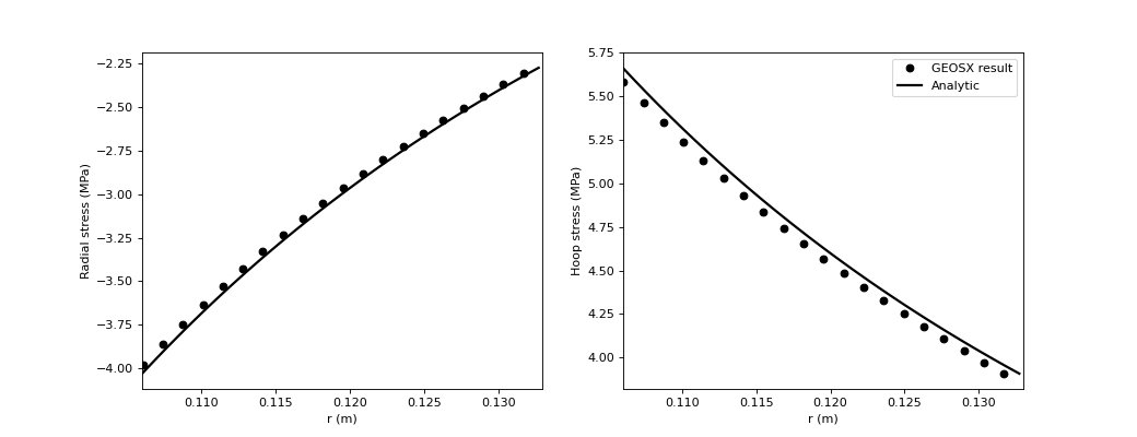
Results and benchmark
A good agreement between the GEOS results and analytical results is shown in the figure below:
To go further
Feedback on this example
This concludes the cased wellbore example. For any feedback on this example, please submit a GitHub issue on the project’s GitHub page.