Cased ThermoElastic Wellbore Problem with Imperfect Contact Interfaces
Problem description
This example uses the coupled THM solver in GEOS to handle a cased wellbore problem subject to a temperature reduction at the casing surface due to cold CO2 injection. The wellbore consists of a steel casing, a cement sheath, and a rock formation. We assume an isotropic linear thermo-elastic behavior for all three materials.
In this example, we do not model any fluid flow. All heat transfers between the casing, cement layer, and rock formation are due only to conduction, and no heat convection is not considered. While GEOS could also simulate convection, we chose to simulate a simplified conduction-only case because semi-analytical solutions exist for this problem. Debonding (separation) is allowed for the casing-cement and cement-rock contact interfaces.
This example is an extension of the pure mechanical debonding example:ref:AdvancedExampleCasedElasticWellbore and the THM problem without debonding Cased ThermoElastic Wellbore Problem. A large portion of the XML files are inherited from those two examples.
Analytical results for the temperature field, the radial displacement, and the radial and hoop stresses can be derived for the axisymmetric plane strain problem with assumptions of debonding at casing-cement or cement-rock interfaces. Note that solutions to this problem are not available in the literature for citation, as it is newly derived by the GEOS team for verifying the numerical results.
Input file
This benchmark example uses no external input files and everything required is contained within two GEOS XML files located at:
inputFiles/wellbore/CasedThermoElasticWellbore_ImperfectInterfaces_base.xml
and
inputFiles/wellbore/CasedThermoElasticWellbore_ImperfectInterfaces_benchmark.xml
The corresponding integrated test is
inputFiles/wellbore/CasedThermoElasticWellbore_ImperfectInterfaces_smoke.xml
Geometry and mesh
The geometry and mesh are defined similarly to the ones in the example Cased ThermoElastic Wellbore Problem. To define the imperfect interfaces between the casing, cement and rock layers, we added the following blocks:
  <Geometry>
    <Cylinder
      name="casingCementInterface"
      firstFaceCenter="{ 0.0, 0.0,  -0.001 }"
      secondFaceCenter="{ 0.0, 0.0, 0.101 }"
      outerRadius="0.17781"
      innerRadius="0.17779"
    />

    <Cylinder
      name="cementRockInterface"
      firstFaceCenter="{ 0.0, 0.0,  -0.001 }"
      secondFaceCenter="{ 0.0, 0.0, 0.101 }"
      outerRadius="0.21273"
      innerRadius="0.21271"
    />
  </Geometry>
Here, we use the Cylinder geometry to select these nodesets. A detailed explanation of the inputs in this block is given in the example Cased Elastic Wellbore Problem.
Material properties
Besides the THM properites of casing, cement and rock as defined in the example Cased ThermoElastic Wellbore Problem, we define properties for the contact interfaces. The mechanical properties of the contact surfaces are defined similarly to the example Cased Elastic Wellbore Problem. Additionally, following blocks define the thermal conductivity of the contact interface.
    <SinglePhaseThermalConductivity
      name="contactThermalCond"
      defaultThermalConductivityComponents="{ 1.0, 1.0, 1.0 }"/>
These properties are used for defining the imperfect contact surfaces as follows:
    <SurfaceElementRegion
      name="Fracture"
      faceBlock="faceElementSubRegion"
      materialList="{ fluid, fractureFilling, frictionLaw, contactThermalCond, hApertureModel }"
      defaultAperture="5.0e-4"/>
As we are using the fully coupled THM solver to solve the thermo-elastic coupled problem, it is also required to define the flow properties for the contact surfaces as follows:
    <CompressibleSolidParallelPlatesPermeability
      name="fractureFilling"
      solidModelName="nullSolid"
      porosityModelName="fracturePorosity"
      permeabilityModelName="fracturePerm"
      solidInternalEnergyModelName="rockInternalEnergy"/>

    <NullModel
      name="nullSolid"/>

    <PressurePorosity
      name="fracturePorosity"
      defaultReferencePorosity="1.00"
      referencePressure="0.0"
      compressibility="0.0"/>

    <ParallelPlatesPermeability
      name="fracturePerm"/>
Boundary and initial conditions
The boundary condition at the casing inner surface and in the far-field are defined identically to the ones of the example Cased ThermoElastic Wellbore Problem. The in-situ initial conditions are also defined in the same way as described in that example. The additional specifications for the contact surfaces are defined identically to the example Cased Elastic Wellbore Problem.
Solvers
The solver for simulating this THM problem with imperfect contact interfaces is defined as follows:
    <SinglePhasePoromechanicsConformingFractures
      name="fractureThermoPoroElasticSolver"
      targetRegions="{ casing, cement, rock, Fracture }"
      initialDt="1e-3"
      flowSolverName="flowSolver"
      solidSolverName="lagrangiancontact"
      logLevel="1"
      isThermal="1">
      <NonlinearSolverParameters
        newtonTol="1.0e-5"
        newtonMaxIter="10"
        maxTimeStepCuts="4"/>
      <LinearSolverParameters
        directParallel="0"
        solverType="direct"/>
    </SinglePhasePoromechanicsConformingFractures>
where the Lagrangian contact solver is identical to the one used in the example Cased Elastic Wellbore Problem and the THM coupled solver is the same as that of the example Cased ThermoElastic Wellbore Problem.
Results and benchmark
The GEOS results of displacement jump across the casing-cement and cement-rock interfaces at 1e5 seconds are shown in the figure below:
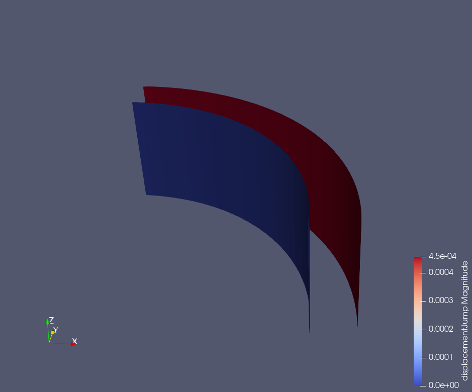
Fig. 71 Displacement jumps across the casing-cement and cement-rock interfaces at 1e5 seconds.
The GEOS results and analytical results for temperature distribution around the cased wellbore are shown in the figures below:
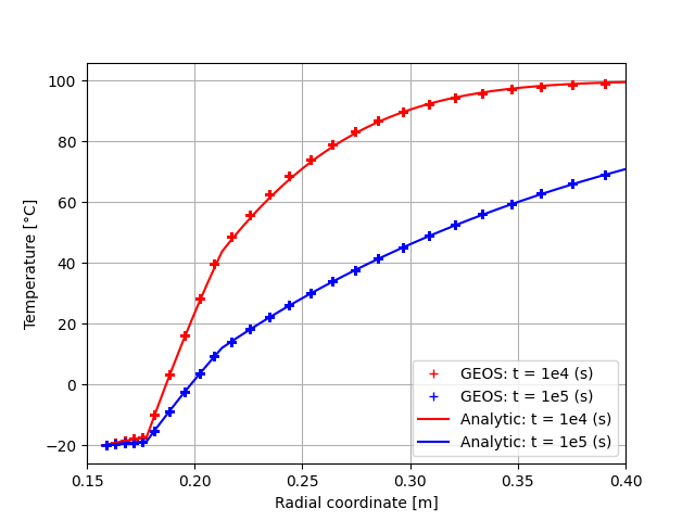
Fig. 72 Temperature field.
and the radial displacement around the wellbore is shown below:
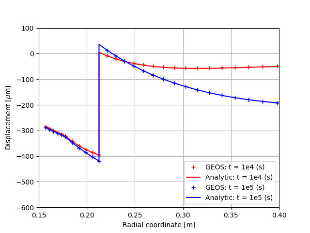
Fig. 73 The displacement field.
The total radial and hoop stress (tangential stress) components computed by GEOS and the reference results are shown in the figure below:
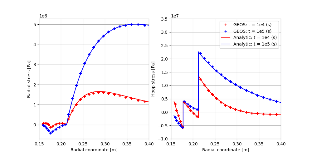
Fig. 74 The stress field.
We can observe a good agreement between GEOS results and the analytical results.
To go further
Feedback on this example
This concludes the cased wellbore example. For any feedback on this example, please submit a GitHub issue on the project’s GitHub page.