Tutorial 1: First Steps
Context
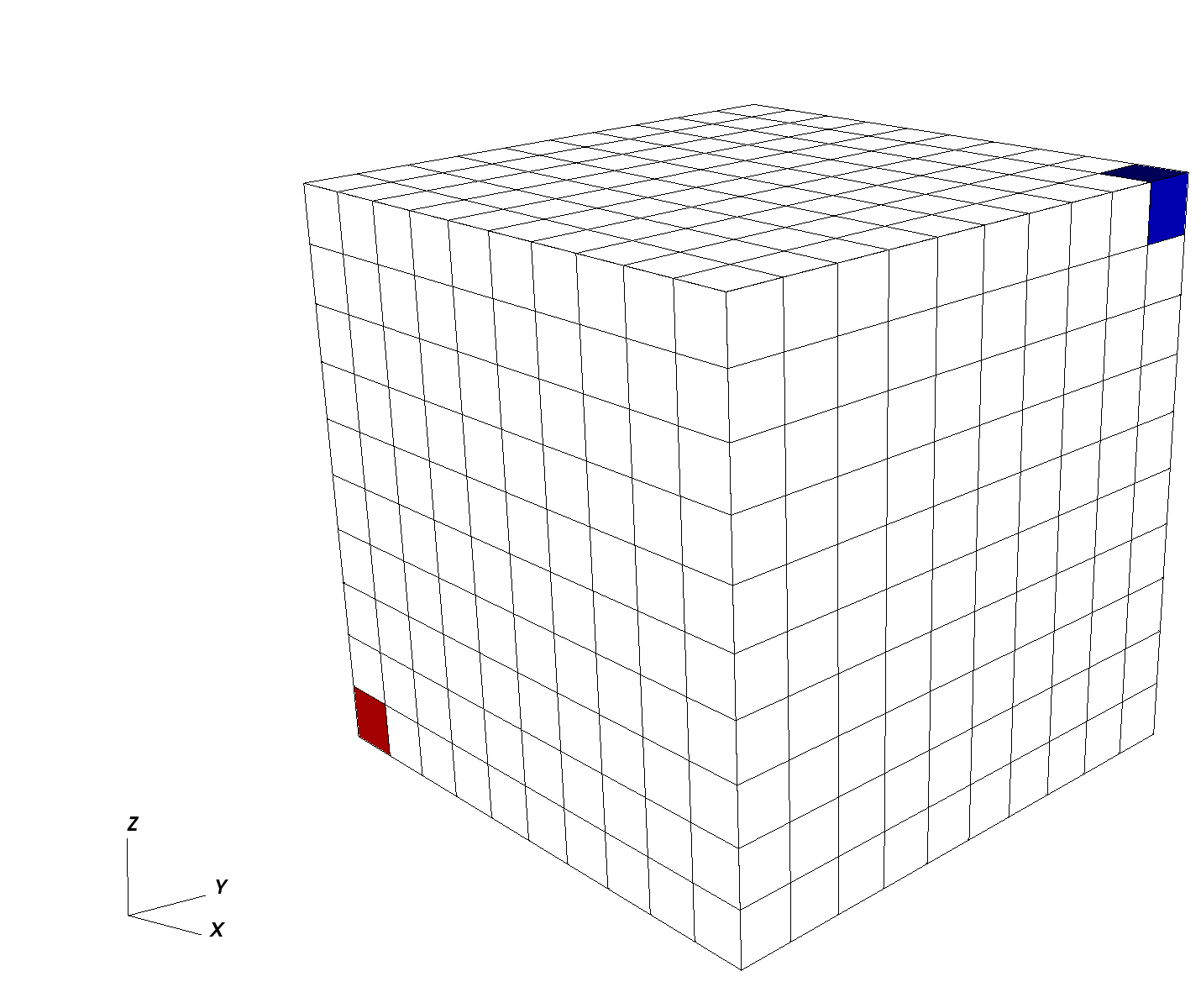
In this tutorial, we use a single-phase flow solver (see Singlephase Flow Solver) to solve for pressure propagation on a 10x10x10 cube mesh with anisotropic permeability values. The pressure source is the lowest-left corner element, and the pressure sink sits at the opposite top corner.

Objectives
At the end of this tutorial you will know:
the basic structure of XML input files used by GEOS,
how to run GEOS on a simple case requiring no external input files,
the basic syntax of a solver block for single-phase problems,
how to control output and visualize results.
Input file
GEOS runs by reading user input information from one or more XML files. For this tutorial, we only need a single GEOS input file located at:
inputFiles/singlePhaseFlow/3D_10x10x10_compressible_smoke.xml
Running GEOS
If our XML input file is called my_input.xml, GEOS runs this file by executing:
/path/to/geosx -i /path/to/my_input.xml
The -i flag indicates the path to the XML input file.
To get help on what other command line input flags GEOS supports, run geosx --help.
Input file structure
XML files store information in a tree-like structure using nested blocks of information called elements.
In GEOS, the root of this tree structure is the element called Problem.
All elements in an XML file are defined by an opening tag (<ElementName>) and end by a corresponding closing tag (</ElementName>). Elements can have properties defined as attributes with key="value" pairs.
A typical GEOS input file contains the following tags:
XML validation tools
If you have not already done so, please use or enable an XML validation tool (see User Guide/Input Files/Input Validation). Such tools will help you identify common issues that may occur when working with XML files.
Note
Common errors come from the fact that XML is case-sensitive, and all opened tags must be properly closed.
Single-phase solver
GEOS is a multiphysics simulator. To find the solution to different physical problems
such as diffusion or mechanical deformation, GEOS uses one or more physics solvers.
The Solvers tag is used to define and parameterize these solvers.
Different combinations of solvers can be applied
in different regions of the domain at different moments of the simulation.
In this first example, we use one type of solver in the entire domain and
for the entire duration of the simulation.
The input file for this tutorial can be found in the repository at
inputFiles/singlePhaseFlow/3D_10x10x10_compressible_smoke.xml, which also includes
inputFiles/singlePhaseFlow/3D_10x10x10_compressible_base.xml.
The solver we are specifying here is a single-phase flow solver.
In GEOS, such a solver is created using a SinglePhaseFVM element.
This type of solver is one among several cell-centered single-phase finite volume methods.
The XML block used to define this single-phase finite volume solver is shown here:
  <Solvers>
    <SinglePhaseFVM
      name="SinglePhaseFlow"
      logLevel="1"
      discretization="singlePhaseTPFA"
      targetRegions="{ mainRegion }">
      <NonlinearSolverParameters
        newtonTol="1.0e-6"
        newtonMaxIter="8"/>
      <LinearSolverParameters
        solverType="gmres"
	preconditionerType="amg"
        krylovTol="1.0e-10"/>
    </SinglePhaseFVM>
  </Solvers>
Each type of solver has a specific set of parameters that are required and some parameters that are optional. Optional values are usually set with sensible default values.
name
First, we register a solver of type SinglePhaseFVM with a user-chosen name,
here SinglePhaseFlow. This unique user-defined name can be almost anything.
However, some symbols are known to cause issues in names : avoid commas, slashes, curly braces.
GEOS is case-sensitive: it makes a distinction between two SinglePhaseFVM solvers called mySolver and MySolver.
Giving elements a name is a common practice in GEOS:
users need to give unique identifiers to objects they define.
That name is the handle to this instance of a solver class.
logLevel
Then, we set a solver-specific level of console logging (logLevel set to 1 here).
Notice that the value (1) is between double-quotes.
This is a general convention for all attributes:
we write key="value" regardless of the value type (integers, strings, lists, etc.).
For logLevel, higher values lead to more console output or intermediate results saved to files.
When debugging, higher logLevel values is often convenient.
In production runs, you may want to suppress most console output.
discretization
For solvers of the SinglePhaseFVM family, one required attribute is a discretization scheme.
Here, we use a Two-Point Flux Approximation (TPFA) finite volume discretization scheme called singlePhaseTPFA.
To know the list of admissible values of an attribute, please see GEOS’s XML schema.
This discretization type must know how to find permeability values that it uses internally to compute transmissibilities.
The permeabilityNames attribute tells the solver the user-defined name (the handle)
of the permeability values that will be defined elsewhere in the input file.
Note that the order of attributes inside an element is not important.
fluidNames, solidNames, targetRegions
Here, we specify a collection of fluids, rocks, and target regions of the mesh on which the solver will apply. Curly brackets are used in GEOS inputs to indicate collections of values (sets or lists). The curly brackets used here are necessary, even if the collection contains a single value. Commas are used to separate members of a set.
Nested elements
Finally, note that other XML elements can be nested inside the Solvers element.
Here, we use specific XML elements to set values for numerical tolerances.
The solver stops when numerical residuals are smaller than
the specified tolerances (convergence is achieved)
or when the maximum number of iterations allowed is exceeded (convergence not achieved).
Mesh
To solve this problem, we need to define a mesh for our numerical calculations. This is the role of the Mesh element.
There are two approaches to specifying meshes in GEOS: internal or external.
The external approach allows to import mesh files created outside GEOS, such as a corner-point grid or an unstructured grid representing complex shapes and structures.
The internal approach uses GEOS’s built-in capability to create simple meshes from a small number of parameters. It does not require any external file information. The geometric complexity of internal meshes is limited, but many practical problems can be solved on such simple grids.
In this tutorial, to keep things self-contained, we use the internal mesh generator. We parameterize it with the InternalMesh element.
  <Mesh>
    <InternalMesh
        name="mesh"
        elementTypes="{ C3D8 }"
        xCoords="{ 0, 10 }"
        yCoords="{ 0, 10 }"
        zCoords="{ 0, 10 }"
        nx="{ 10 }"
        ny="{ 10 }"
        nz="{ 10 }"
        cellBlockNames="{ cellBlock }"/>
  </Mesh>
name
Just like for solvers, we register the InternalMesh element using a unique name attribute.
Here the InternalMesh object is instantiated with the name mesh.
elementTypes
We specify the collection of elements types that this mesh contains.
Tetrahedra, hexahedra, and wedges are examples of element types.
If a mesh contains different types of elements (a hybrid mesh),
we should indicate this here by listing all unique types of elements in curly brackets.
Keeping things simple, our element collection has only one type of element: a C3D8 type representing a hexahedral element (linear 8-node brick).
A mesh can contain several geometrical types of elements.
For numerical convenience, elements are aggregated by types into cellBlocks.
Here, we only have linear 8-node brick elements, so the entire domain is one object called cellBlock.
xCoords, yCoords, zCoords, nx, ny, nz
This specifies the spatial arrangement of the mesh elements.
The mesh defined here goes from coordinate x=0 to x=10 in the x-direction, with nx=10 subdivisions along this segment.
The same is true for the y-dimension and the z-dimension.
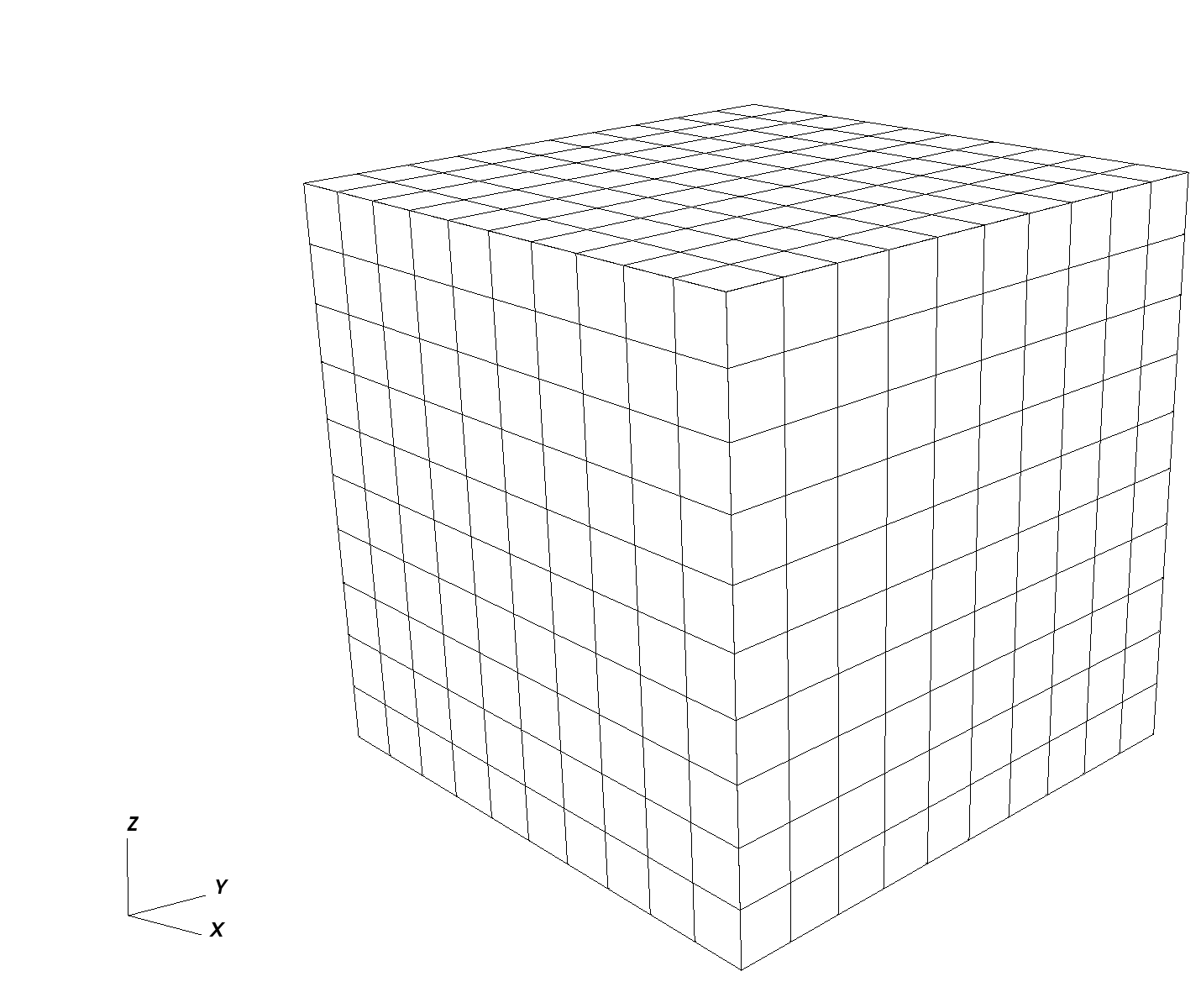
Our mesh is a cube of 10x10x10=1,000 elements with a bounding box defined by corner coordinates (0,0,0) and (10,10,10).

Geometry
The Geometry tag allows users to capture subregions of a mesh and assign them a unique name.
Here, we name two Box elements, one for the location of the source and one for the sink.
Pressure values are assigned to these named regions elsewhere in the input file.
The pressure source is the element in the (0,0,0) corner of the domain, and the sink is the element in the (10,10,10) corner.
For an element to be inside a geometric region, it must have all its vertices strictly inside that region. Consequently, we need to extend the geometry limits a small amount beyond the actual coordinates of the elements to catch all vertices. Here, we use a safety padding of 0.01.
  <Geometry>
    <Box
      name="source"
      xMin="{ -0.01, -0.01, -0.01 }"
      xMax="{ 1.01, 1.01, 1.01 }"/>

    <Box
      name="sink"
      xMin="{ 8.99, 8.99, 8.99 }"
      xMax="{ 10.01, 10.01, 10.01 }"/>
  </Geometry>
There are several methods to achieve similar conditions (Dirichlet boundary condition on faces, etc.).
The Box defined here is one of the simplest approaches.

Events
In GEOS, we call Events anything that happens at a set time or frequency.
Events are a central element for time-stepping in GEOS,
and a dedicated section just for events is necessary to give them the treatment they deserve.
For now, we focus on three simple events: the time at which we wish the simulation to end (maxTime),
the times at which we want the solver to perform updates,
and the times we wish to have simulation output values reported.
In GEOS, all times are specified in seconds, so here maxTime=5000.0 means that the simulation will run from time 0 to time 5,000 seconds.
If we focus on the PeriodicEvent elements, we see :
A periodic solver application: this event is named
solverApplications. With the attributeforceDt=20, it tells the solver to compute results at 20-second time intervals. We know what this event does by looking at itstargetattribute: here, from time 0 tomaxTimeand with a forced time step of 20 seconds, we instruct GEOS to call the solver registered asSinglePhaseFlow. Note the hierarchical structure of the target formulation, using ‘/’ to indicate a specific named instance (SinglePhaseFlow) of an element (Solvers). If the solver needs to take smaller time steps, it is allowed to do so, but it will have to compute results for every 20-second increment between time zero andmaxTimeregardless of possible intermediate time steps.An output event: this event is used for reporting purposes and instructs GEOS to write out results at specific frequencies. Here, we need to see results at every 100-second increment. This event triggers a full application of solvers, even if solvers were not summoned by the previous event. In other words, an output event will force an application of solvers, possibly in addition to the periodic events requested directly.
  <Events maxTime="5000.0">
    <PeriodicEvent
        name="solverApplications"
        forceDt="20.0"
        target="/Solvers/SinglePhaseFlow"/>
    <PeriodicEvent
        name="outputs"
        timeFrequency="100.0"
        target="/Outputs/siloOutput"/>
  </Events>
Numerical methods
GEOS comes with several useful numerical methods.
In the Solvers elements, for instance, we had specified to use a two-point flux approximation
as discretization scheme for the finite volume single-phase solver.
Now to use this scheme, we need to supply more details in the NumericalMethods element.
  <NumericalMethods>
    <FiniteVolume>
      <TwoPointFluxApproximation
        name="singlePhaseTPFA"
        />
    </FiniteVolume>
  </NumericalMethods>
Note that in GEOS, there is a difference between physics solvers and numerical methods. Their parameterizations are thus independent. We can have multiple solvers using the same numerical scheme but with different tolerances, for instance.
The available numerical methods and their options are listed in the GEOS XML schema documentation which may be found by using the search function in the documentation.
Regions
In GEOS, ElementsRegions are used to attach material properties
to regions of elements.
Here, we use only one CellElementRegion to represent the entire domain (user name: mainRegion).
It contains all the blocks called cellBlock defined in the mesh section.
We specify the materials contained in that region using a materialList.
Several materials coexist in cellBlock, and we list them using their user-defined names:
water and rock in this exemple.
Each material is a definition of physical properties.
  <ElementRegions>
    <CellElementRegion
      name="mainRegion"
      cellBlocks="{ * }"
      materialList="{ water, rock }"/>
  </ElementRegions>
Constitutive models
The Constitutive element attaches physical properties to all materials contained in the domain.
The physical properties of the materials
defined as water, rockPorosity, and rockPerm are provided here,
each material being derived from a different material type:
CompressibleSinglePhaseFluid
for the water, PressurePorosity for the rock porosity, and
ConstantPermeability for rock permeability.
The list of attributes differs between these constitutive materials.
  <Constitutive>
    <CompressibleSinglePhaseFluid
      name="water"
      defaultDensity="1000"
      defaultViscosity="0.001"
      referencePressure="0.0"
      compressibility="5e-10"
      viscosibility="0.0"/>

    <CompressibleSolidConstantPermeability
      name="rock"
      solidModelName="nullSolid"
      porosityModelName="rockPorosity"
      permeabilityModelName="rockPerm"/>

    <NullModel
      name="nullSolid"/>

    <PressurePorosity
      name="rockPorosity"
      defaultReferencePorosity="0.05"
      referencePressure="0.0"
      compressibility="1.0e-9"/>

    <ConstantPermeability
      name="rockPerm"
      permeabilityComponents="{ 1.0e-12, 1.0e-12, 1.0e-15 }"/>
  </Constitutive>
The names water, rockPorosity and rockPerm are defined by the user
as handles to specific instances of physical materials.
GEOS uses S.I. units throughout, not field units.
Pressures, for instance, are in Pascal, not psia.
The x- and y-permeability are set to 1.0e-12 m2 corresponding to approximately to 1 Darcy.
We have used the handles water, rockPorosity and rockPerm in the input file
in the ElementRegions section of the XML file,
before the registration of these materials took place here, in Constitutive element.
Note
This highlights an important aspect of using XML in GEOS: the order in which objects are registered and used in the XML file is not important.
Defining properties
In the FieldSpecifications section, properties such as source and sink pressures are set.
GEOS offers a lot of flexibility to specify field values through space and time.
Spatially, in GEOS, all field specifications are associated to a target object on which the field values are mounted. This allows for a lot of freedom in defining fields: for instance, one can have volume property values attached to a subset of volume elements of the mesh, or surface properties attached to faces of a subset of elements.
For each FieldSpecification, we specify a name, a fieldName (this name is used by solvers or numerical methods), an objectPath, setNames and a scale. The ObjectPath is important and it reflects the internal class hierarchy of the code.
Here, for the fieldName pressure, we assign the value defined by scale (5e6 Pascal)
to one of the ElementRegions (class) called mainRegions (instance).
More specifically, we target the elementSubRegions called cellBlock
(this contains all the C3D8 elements, effectively all the domain). The setNames allows to use the elements defined in Geometry, or use everything in the object path (using the all).
  <FieldSpecifications>
    <FieldSpecification
      name="initialPressure"
      initialCondition="1"
      setNames="{ all }"
      objectPath="ElementRegions/mainRegion/cellBlock"
      fieldName="pressure"
      scale="5e6"/>

    <FieldSpecification
      name="sourceTerm"
      objectPath="ElementRegions/mainRegion/cellBlock"
      fieldName="pressure"
      scale="1e7"
      setNames="{ source }"/>

    <FieldSpecification
      name="sinkTerm"
      objectPath="ElementRegions/mainRegion/cellBlock"
      fieldName="pressure"
      scale="0.0"
      setNames="{ sink }"/>
  </FieldSpecifications>
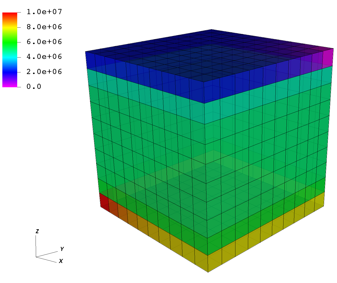
The image below shows the pressures after the very first time step, with the domain initialized at 5 MPa, the sink at 0 MPa on the top right, and the source in the lower left corner at 10 MPa.

Output
In order to retrieve results from a simulation,
we need to instantiate one or multiple Outputs.
Here, we define a single object of type Silo.
Silo is a library and a format for reading and writing a wide variety of scientific data.
Data in Silo format can be read by VisIt.
This Silo output object is called siloOutput.
We had referred to this object already in the Events section:
it was the target of a periodic event named outputs.
You can verify that the Events section is using this object as a target.
It does so by pointing to /Outputs/siloOutput.
  <Outputs>
    <Silo
      name="siloOutput"/>
  </Outputs>
GEOS currently supports outputs that are readable by VisIt and Kitware’s Paraview, as well as other visualization tools. In this example, we only request a Silo format compatible with VisIt.
All elements are now in place to run GEOS.
Running GEOS
The command to run GEOS is
path/to/geosx -i path/to/this/xml_file.xml
Note that all paths for files included in the XML file are relative to this XML file.
While running GEOS, it logs status information on the console output with a verbosity
that is controlled at the object level, and
that can be changed using the logLevel flag.
The first few lines appearing to the console are indicating that the XML elements are read and registered correctly:
Adding Solver of type SinglePhaseFVM, named SinglePhaseFlow
Adding Mesh: InternalMesh, mesh
Adding Geometric Object: Box, source
Adding Geometric Object: Box, sink
Adding Event: PeriodicEvent, solverApplications
Adding Event: PeriodicEvent, outputs
Adding Output: Silo, siloOutput
Adding Object CellElementRegion named mainRegion from ObjectManager::Catalog.
  mainRegion/cellBlock/water is allocated with 1 quadrature points.
  mainRegion/cellBlock/rock is allocated with 1 quadrature points.
  mainRegion/cellBlock/rockPerm is allocated with 1 quadrature points.
  mainRegion/cellBlock/rockPorosity is allocated with 1 quadrature points.
  mainRegion/cellBlock/nullSolid is allocated with 1 quadrature points.
Then, we go into the execution of the simulation itself:
Time: 0s, dt:20s, Cycle: 0
    Attempt:  0, NewtonIter:  0
    ( R ) = ( 5.65e+00 ) ;
    Attempt:  0, NewtonIter:  1
    ( R ) = ( 2.07e-04 ) ;
    Last LinSolve(iter,res) = (  63, 8.96e-11 ) ;
    Attempt:  0, NewtonIter:  2
    ( R ) = ( 9.86e-11 ) ;
    Last LinSolve(iter,res) = (  70, 4.07e-11 ) ;
Each time iteration at every 20s interval is logged to console, until the end of the simulation at maxTime=5000:
Time: 4980s, dt:20s, Cycle: 249
    Attempt:  0, NewtonIter:  0
    ( R ) = ( 4.74e-09 ) ;
    Attempt:  0, NewtonIter:  1
    ( R ) = ( 2.05e-14 ) ;
    Last LinSolve(iter,res) = (  67, 5.61e-11 ) ;
SinglePhaseFlow: Newton solver converged in less than 4 iterations, time-step required will be doubled.
Cleaning up events
Umpire            HOST sum across ranks:   14.8 MB
Umpire            HOST         rank max:   14.8 MB
total time                         5.658s
initialization time                0.147s
run time                           3.289s
All newton iterations are logged along with corresponding nonlinear residuals for each time iteration.
In turn, for each newton iteration, LinSolve provides the number of linear iterations and the final residual reached by the linear solver.
Information on run times, initialization times, and maximum amounts of
memory (high water mark) are given at the end of the simulation, if successful.
Congratulations on completing this first run!
Visualization
Here, we have requested results to be written in Silo, a format compatible with VisIt. To visualize results, open VisIt and directly load the database of simulation output files.
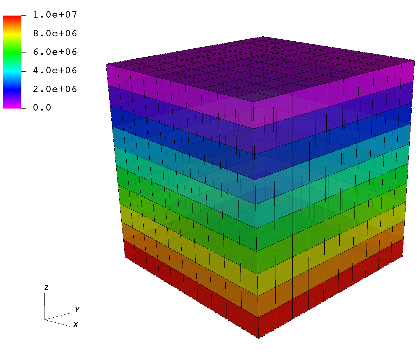
After a few time step, pressure between the source and sink are in equilibrium, as shown on the representation below.

To go further
Feedback on this tutorial
This concludes the single-phase internal mesh tutorial. For any feedback on this tutorial, please submit a GitHub issue on the project’s GitHub page.
For more details
More on single-phase flow solvers, please see Singlephase Flow Solver.
More on meshes, please see Meshes.
More on events, please see Event Management.