Shear Slip Along a Frictionless Vertical Fault
Context
This example is a companion to Shear Stress Along a Stable Vertical Fault. It uses the same geometry, mesh, workflows (external and internal), solvers, discretization methods, constitutive models, and initial and boundary conditions. The only difference is the strength of the fault: here, both the friction coefficient and the cohesion are set to zero, so that the fault slips upon reservoir depletion. The model computes displacement discontinuities (fault slip upon reactivation) along the frictionless fault, which are verified against the corresponding analytical solution (Jansen and Meulenbroek, 2022).
Please refer to Shear Stress Along a Stable Vertical Fault for a complete description of the problem and of the XML input files. Only the differences with that case are described below.
Input file
The xml input files for the test case with external workflow are located at:
inputFiles/poromechanicsFractures/Contact/AugmentedLagrangianMultipliers/ALM_verticalFault_base.xml
inputFiles/poromechanicsFractures/Contact/AugmentedLagrangianMultipliers/verticalFault_unstable_ESG_benchmark.xml
The xml input files for the test case with internal workflow are located at:
inputFiles/poromechanicsFractures/Contact/AugmentedLagrangianMultipliers/ALM_verticalFault_base.xml
inputFiles/poromechanicsFractures/Contact/AugmentedLagrangianMultipliers/verticalFault_unstable_ISG_benchmark.xml
Corresponding mesh files and a python script for post-processing the simulation results are also provided:
inputFiles/poromechanicsFractures/MESH
src/docs/sphinx/advancedExamples/validationStudies/faultMechanics/slippedVerticalFault/unstableFaultFigure.py
Differences with the stable fault case
A frictionless configuration is achieved by setting both the friction coefficient and the cohesion of the fault contact law (fractureContact) to zero, enabling shear slip. Depletion then induces localized slip along the fault planes in contact with the reservoir.
    <PorousElasticIsotropic
      name="porousRock"
      solidModelName="rock"
      porosityModelName="rockPorosity"
      permeabilityModelName="rockPerm" />

    <ElasticIsotropic
      name="rock"
      defaultDensity="2650.0"
      defaultYoungModulus="14.95e9"
      defaultPoissonRatio="0.15" />

    <CompressibleSinglePhaseFluid
      name="water"
      defaultDensity="1020"
      defaultViscosity="0.001"
      referencePressure="35e6"
      referenceDensity="1020"
      compressibility="1.e-20"
      referenceViscosity="0.001"
      viscosibility="0.0" />

    <BiotPorosity
      name="rockPorosity"
      defaultGrainBulkModulus="7.119e10"
      defaultReferencePorosity="0.15" />

    <ConstantPermeability
      name="rockPerm"
      permeabilityComponents="{1.0e-18, 1.0e-18, 1.0e-18}" />

    <CompressibleSolidParallelPlatesPermeability
      name="faultFilling"
      solidModelName="nullSolid"
      porosityModelName="fracturePorosity"
      permeabilityModelName="fracturePerm" />

    <PressurePorosity
      name="fracturePorosity"
      defaultReferencePorosity="1.00"
      referencePressure="0e6"
      compressibility="0.0" />

    <ParallelPlatesPermeability
      name="fracturePerm" />

    <Coulomb
      name="fractureContact"
      defaultCohesion="0.0"
      defaultFrictionCoefficient="0.0" />

    <HydraulicApertureTable
      name="hApertureModel"
      apertureTableName="apertureTable" />

    <NullModel
      name="nullSolid" />
The fault parameters of both cases are compared in the following table. All other parameters are identical to those listed in Shear Stress Along a Stable Vertical Fault.
Symbol |
Parameter |
Unit |
Stable fault |
Frictionless fault |
|---|---|---|---|---|
|
Friction Coefficient |
[-] |
1.0 |
0.0 |
|
Cohesion |
[MPa] |
5.0 |
0.0 |


Inspecting results
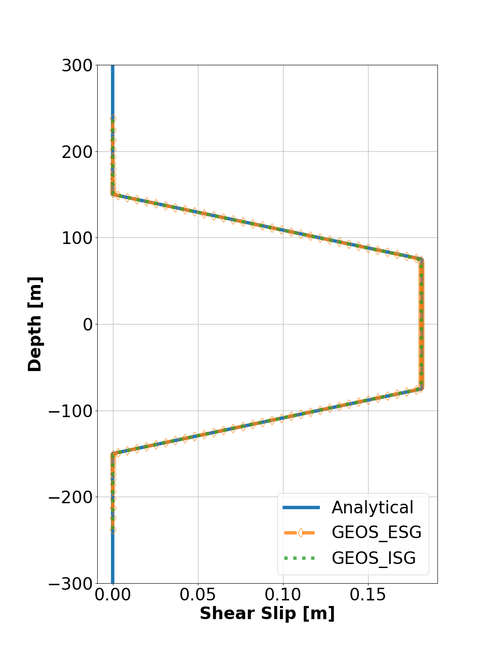
The figure below presents a comparison between GEOS simulations (dashed lines) and analytical solutions (solid curves) for shear slip along a frictionless fault plane. The results demonstrate that GEOS reliably captures the mechanical deformation of the faulted reservoir and achieves excellent agreement with the analytical solutions for both workflows.
Furthermore, a mesh convergence study is also performed. For isotropic meshes (with near-unity aspect ratio in the x–z plane), the L2 error norm approaches the theoretical convergence rate, confirming the robustness and accuracy of the implemented ALM solver.
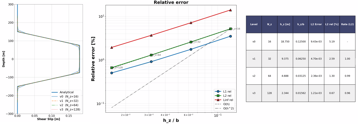
Fig. 33 Convergence of the relative 𝐿2-error for shear slip
To go further
Feedback on this example
For any feedback on this example, please submit a GitHub issue on the project’s GitHub page.