Meshes
The purpose of this document is to explain how users and developers interact with mesh data. This section describes how meshes are handled and stored in GEOS.
There are two possible methods for generating a mesh: either by using GEOS’s internal mesh generator (for Cartesian meshes only), or by importing meshes from various common mesh file formats. This latter options allows one to work with more complex geometries, such as unstructured meshes comprised of a variety of element types (polyhedral elements).
Note
GEOS uses a right-handed Cartesian coordinate system (X: right, Y: forward, Z: upward) that is consistently applied throughout the mesh definition and discretization processes. This convention affects mesh topology, and finite element / volume computations.
Internal Mesh Generation
Basic Example
The Internal Mesh Generator allows one to quickly build simple cartesian grids and divide them into several regions. The following attributes are supported in the input block for InternalMesh:
XML Element: InternalMesh
Name |
Type |
Default |
Description |
|---|---|---|---|
cellBlockNames |
groupNameRef_array |
required |
Names of each mesh block |
checkEulerCharacteristic |
integer |
0 |
When set to 1, compute the Euler-Poincaré characteristic χ = V − E + F − C after the mesh is loaded and issue a warning if χ ≠ 1. χ = 1 is expected for a single connected solid mesh without interior voids. Non-unity values may indicate multiple disconnected bodies, interior voids, or non-manifold topology. Default: 0 (disabled). |
elementTypes |
string_array |
required |
Element types of each mesh block. Use “C3D8” for linear brick element. Possible values are: Vertex, BEAM, C2D3, C2D4, Polygon, C3D4, C3D5, C3D6, C3D8, PentagonalPrism, HexagonalPrism, HeptagonalPrism, OctagonalPrism, NonagonalPrism, DecagonalPrism, HendecagonalPrism, Polyhedron. |
name |
groupName |
required |
A name is required for any non-unique nodes |
nx |
integer_array |
required |
Number of elements in the x-direction within each mesh block |
ny |
integer_array |
required |
Number of elements in the y-direction within each mesh block |
nz |
integer_array |
required |
Number of elements in the z-direction within each mesh block |
positionTolerance |
real64 |
1e-10 |
A position tolerance to verify if a node belong to a nodeset |
trianglePattern |
integer |
0 |
Pattern by which to decompose the hex mesh into wedges |
xBias |
real64_array |
{1} |
Bias of element sizes in the x-direction within each mesh block (dx_left=(1+b)*L/N, dx_right=(1-b)*L/N) |
xCoords |
real64_array |
required |
x-coordinates of each mesh block vertex |
yBias |
real64_array |
{1} |
Bias of element sizes in the y-direction within each mesh block (dy_left=(1+b)*L/N, dx_right=(1-b)*L/N) |
yCoords |
real64_array |
required |
y-coordinates of each mesh block vertex |
zBias |
real64_array |
{1} |
Bias of element sizes in the z-direction within each mesh block (dz_left=(1+b)*L/N, dz_right=(1-b)*L/N) |
zCoords |
real64_array |
required |
z-coordinates of each mesh block vertex |
InternalWell |
node |
||
Region |
node |
||
VTKWell |
node |
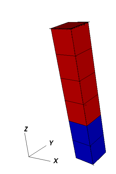
The following is an example XML <mesh> block, which will generate a vertical beam with two CellBlocks (one in red and one in blue in the following picture).
<Mesh>
  <InternalMesh name="mesh"
                elementTypes="{ C3D8 }"
                xCoords="{ 0, 1 }"
                yCoords="{ 0, 1 }"
                zCoords="{ 0, 2, 6 }"
                nx="{ 1 }"
                ny="{ 1 }"
                nz="{ 2, 4 }"
                cellBlockNames="{ cb1, cb2 }"/>
</Mesh>
namethe name of the mesh bodyelementTypesthe type of the elements that will be generated.xCoordList ofxcoordinates of the boundaries of theCellBlocksyCoordList ofycoordinates of the boundaries of theCellBlockszCoordList ofzcoordinates of the boundaries of theCellBlocksnxList containing the number of cells inxdirection within theCellBlocksnyList containing the number of cells inydirection within theCellBlocksnzList containing the number of cells inzdirection within theCellBlockscellBlockNamesList containing the names of theCellBlocks
Mesh Bias
The internal mesh generator is capable of producing meshes with element sizes that vary smoothly over space.
This is achieved by specifying xBias, yBias, and/or zBias fields.
(Note: if present, the length of these must match nx, ny, and nz, respectively, and each individual value must be in the range (-1, 1).)
For a given element block, the average element size will be
![dx_{average}[i] = \frac{xCoords[i+1]-xCoords[i]}{nx[i]},](../../../_images/math/818f68bc2df1aba2796aa09dfd843080e376afdf.svg)
the element on the left-most side of the block will have size
![dx_{left}[i] = (1 + xBias[i]) \cdot dx_{average}[i],](../../../_images/math/13d554057813521314af4927e8bc3e50dd997279.svg)
and the element on the right-most side will have size
![dx_{right}[i] = (1 - xBias[i]) \cdot dx_{average}[i].](../../../_images/math/b4ba98daf9223e2818b5e463606d44a1dcbcb467.svg)
The following are the two most common scenarios that occur while designing a mesh with bias:
The size of the block and the element size on an adjacent region are known. Assuming that we are to the left of the target block, the appropriate bias would be:
![xBias[i] = 1 - \frac{nx[i] \cdot dx_{left}[i+1]}{xCoords[i+1]-xCoords[i]}](../../../_images/math/787a94ac897425e7ed6f00679723d257577bd172.svg)
The bias of the block and the element size on an adjacent region are known. Again, assuming that we are to the left of the target block, the appropriate size for the block would be:
![xCoords[i+1]-xCoords[i] = \frac{nx[i] \cdot dx_{left}[i+1]}{1 - xBias[i]}](../../../_images/math/b40cc1044173d9cd10b9cbb51b3091193a779d21.svg)
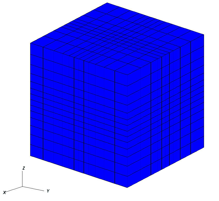
The following is an example of a mesh block along each dimension, and an image showing the corresponding mesh. Note that there is a core region of elements with zero bias, and that the transitions between element blocks are smooth.
  <Mesh>
    <InternalMesh
      name="mesh1"
      elementTypes="{ C3D8 }"
      xCoords="{ -10, -1, 0, 1, 10 }"
      yCoords="{ -10, -1, 0, 1, 10 }"
      zCoords="{ -10, -1, 0, 1, 10 }"
      nx="{ 4, 1, 1, 4 }"
      ny="{ 5, 1, 1, 5 }"
      nz="{ 6, 1, 1, 6 }"
      xBias="{ 0.555, 0, 0, -0.555 }"
      yBias="{ 0.444, 0, 0, -0.444 }"
      zBias="{ 0.333, 0, 0, -0.333 }"
      cellBlockNames="{ cb1 }"/>
  </Mesh>

  <Solvers>
    <SolidMechanicsLagrangianFEM
      name="lagsolve"
      strainTheory="1"
      cflFactor="0.25"
      discretization="FE1"
      targetRegions="{ Region2 }"
      />
  </Solvers>
Advanced Cell Block Specification
It’s possible to generate more complex CellBlock using the InternalMeshGenerator.
For instance, the staircase example is a model which is often used in GEOS as an integrated
test. It defines CellBlocks in the three directions to generate a staircase-like model
with the following code.
<Mesh>
  <InternalMesh name="mesh1"
                elementTypes="{C3D8}"
                xCoords="{0, 5, 10}"
                yCoords="{0, 5, 10}"
                zCoords="{0, 2.5, 5, 7.5, 10}"
                nx="{5, 5}"
                ny="{5, 5}"
                nz="{3, 3, 3, 3}"
                cellBlockNames="{cb-0_0_0, cb-1_0_0, cb-0_1_0, cb-1_1_0,
                                 cb-0_0_1, cb-1_0_1, cb-0_1_1, cb-1_1_1,
                                 cb-0_0_2, cb-1_0_2, cb-0_1_2, cb-1_1_2,
                                 cb-0_0_3, cb-1_0_3, cb-0_1_3, cb-1_1_3}"/>
</Mesh>

<ElementRegions>
   <CellElementRegion name="Channel"
                  cellBlocks="{cb-1_0_0, cb-0_0_0, cb-0_0_1, cb-0_1_1, cb-0_1_2, cb-1_1_2, cb-1_1_3, cb-1_0_3}"
                  materialList="{fluid1, rock, relperm}"/>
   <CellElementRegion name="Barrier"
                  cellBlocks="{cb-0_1_0, cb-1_1_0, cb-1_1_1, cb-1_0_1, cb-1_0_2, cb-0_0_2, cb-0_0_3, cb-0_1_3}"
                  materialList="{}"/>
</ElementRegions>
Thus, the generated mesh will be :

Note that CellBlocks are ordered following the natural IJK logic, with indices increasing first in I (x-direction), then in J (y-direction) and last in K (z-direction).
Using an External Mesh
Supported Formats
GEOS provides features to run simulations on unstructured meshes. It uses VTK to read the external meshes and its API to write it into the GEOS mesh data structure.
The supported mesh elements for volume elements consist of the following:
4-node tetrahedra,
5-node pyramids,
6-node wedges,
8-node hexahedra,
n-gonal prisms (n = 7, …, 11).
The mesh can be divided in several regions.
These regions are intended to support different physics
or to define different constitutive properties.
By default, we use the attribute field to define the regions.
Importing the Mesh
Importing regions
Several blocks are involved to import an external mesh into GEOS, defined in the XML input file.
These are the <Mesh> block and the <CellElementRegions> block.
The mesh block has the following syntax:
<Mesh>
  <VTKMesh
    name="MyMeshName"
    logLevel="1"
    file="/path/to/the/mesh/file.vtk"
    regionAttribute="myAttribute" />
</Mesh>
- ..note::
We advise users to use absolute path to the mesh file, and recommend the use of a
logLevelof 1 or more to obtain some information about the mesh import, including the list of regions that are imported with their names, which is particularly useful to fill the field of theCellElementRegionsblock (see below). Some information about the imported surfaces is also provided.
GEOS uses ElementRegions to support different physics or to define different constitutive properties.
The ElementRegions block can contain several CellElementRegion blocks. A CellElementRegion
is defined as a set of cell-blocks, which are sets of elements with the same element
geometry, defined within the cellBlocks attribute.
The naming of cell-blocks depends on if the mesh contains a data array which has the
same value as the regionAttribute of the VTKMesh (which is attribute by default).
This attribute is used to define regions in the vtu file and assign the cells to a given region.
For now, loaded regions has the following limitations:
- The regionAttribute can only refer to integer values (no texts),
- Each element can belong to only one region.
In GEOS, there are three different ways to select cellBlocks in a CellElementRegion:
Using a list of the desired
regionAttributevalues. I.e."{ 1, 2 }"selects all the cell-blocks of theregionAttribute1 and 2.Using a list of the exact cell-blocks names from the mesh to contain in this CellElementRegion. I.e.
{ 1_tetrahedra, 1_pyramid, 1_hexahedra, 2_tetrahedra, 2_pyramid, 2_hexahedra }Using a list of fnmatch patterns to match cell-block names to add them in this
CellElementRegion. I.e.{ * }selects every elements,{ 1_* }selects the{ 1_tetrahedra, 1_pyramid, 1_hexahedra }cell-blocks.
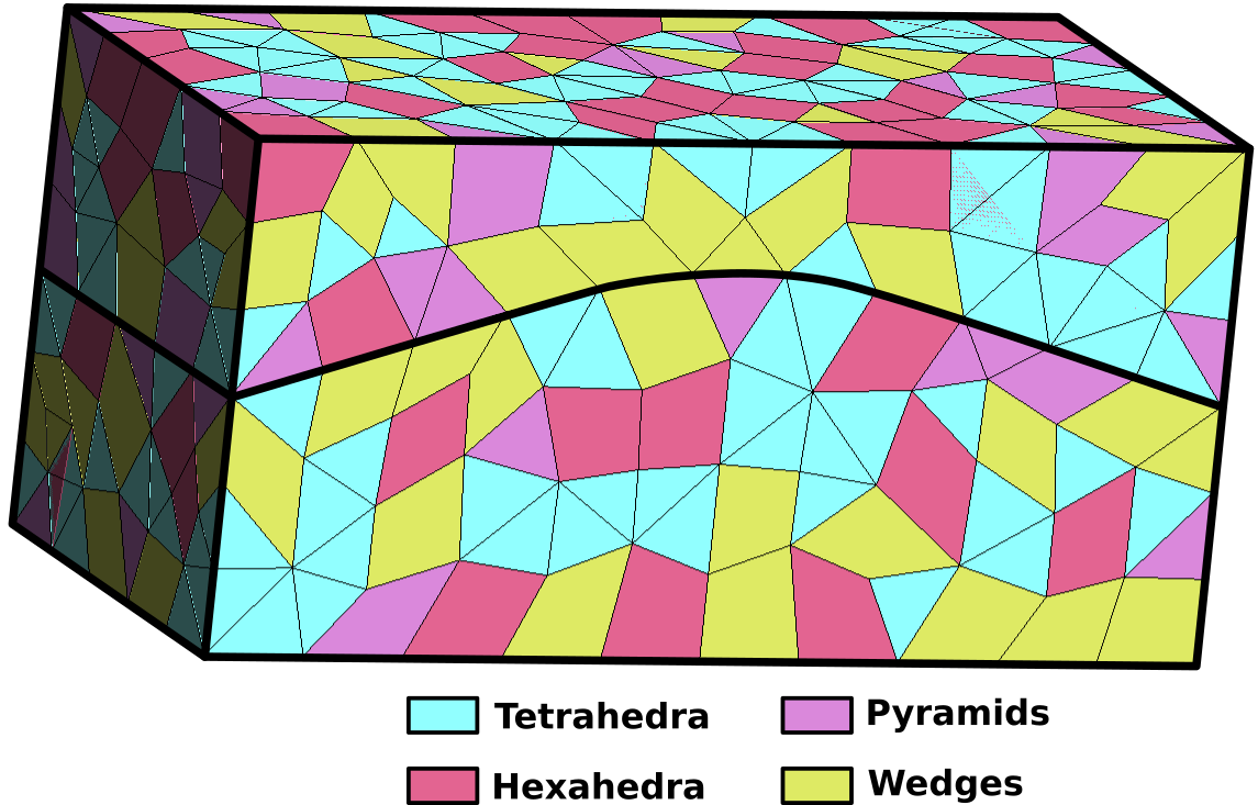
In the example presented above, the mesh is is composed of two regions. Each region contains 4 element types.
If the vtu file contains an attribute equals to the
regionAttributeof theVTKMesh, then allcellBlockare named with this convention:regionAttribute_elementType. Let’s assume that the top region of the exemple above hasmyAttributeto 1, and that the bottom region hasmyAttributeto 2,If we want the
CellElementRegionto contain all the cells, we write:
<!-- Method one: Use `*` to match all cellBlock names automatically.
                 "{ [1-2]_* }" would have an equivalent result (range selection). -->
<ElementRegions>
  <CellElementRegion
    name="MyRegion"
    cellBlocks="{ * }"
    materialList="{ water, rock }" />
</ElementRegions>

<!-- Method two: Use `1, 2` to target the mesh regions. -->
<ElementRegions>
  <CellElementRegion
    name="MyRegion"
    cellBlocks="{ 1, 2 }"
    materialList="{ water, rock }" />
</ElementRegions>

<!-- Method three: manually name all cell-blocks. -->
<ElementRegions>
  <CellElementRegion
    name="MyRegion"
    cellBlocks="{ 1_hexahedra, 1_wedges, 1_tetrahedra, 1_pyramids, 2_hexahedra, 2_wedges, 2_tetrahedra, 2_pyramids }"
    materialList="{ water, rock }" />
</ElementRegions>
If we want two
CellElementRegionwith the top and bottom regions separated, we write:
<!-- Method one: Use the `regionAttribute` to select region '1' in 'Top' region, and region '2' in 'Bot' region. -->
<ElementRegions>
  <CellElementRegion
    name="Top"
    cellBlocks="{ 1 }"
    materialList="{ water, rock }"/>
  <CellElementRegion
    name="Bot"
    cellBlocks="{ 2 }"
    materialList="{ water, rock }" />
</ElementRegions>

<!-- Method two: Use `cellBlocks` for the same purpose, but by matching the name patterns. -->
<ElementRegions>
  <CellElementRegion
    name="Top"
    cellBlocks="{ 1_* }"
    materialList="{ water, rock }"/>
  <CellElementRegion
    name="Bot"
    cellBlocks="{ 2_* }"
    materialList="{ water, rock }" />
</ElementRegions>

<!-- Method three: manually name the cell-blocks in the same regions. -->
<ElementRegions>
  <CellElementRegion
    name="Top"
    cellBlocks="{ 1_hexahedra, 1_wedges, 1_tetrahedra, 1_pyramids }"
    materialList="{ water, rock }"/>
  <CellElementRegion
    name="Bot"
    cellBlocks="{ 2_hexahedra, 2_wedges, 2_tetrahedra, 2_pyramids }"
    materialList="{ water, rock }" />
</ElementRegions>
If the vtu file does not contain any region attribute field, then all the cells are grouped in a single region, and cellBlock names consist of just the cell types (hexahedra, wedges, tetrahedra, etc). Then in the exemple above, the
ElementRegionscan be defined as bellow:
<!-- Method one: Use `*` to match all cellBlock names automatically.  -->
<ElementRegions>
  <CellElementRegion
    name="MyRegion"
    cellBlocks="{ * }"
    materialList="{ water, rock }" />
</ElementRegions>

<!-- Exemple two: manually name the desired cell-blocks. -->
<ElementRegions>
  <CellElementRegion
    name="MyRegion"
    cellBlocks="{ hexahedra, wedges, tetrahedra, pyramids }"
    materialList="{ water, rock }" />
</ElementRegions>

<!-- Exemple three: Use only the tetrahedric cell-blocks on this region (see the warning below) -->
<ElementRegions>
  <CellElementRegion
    name="MyRegion"
    cellBlocks="{ tetrahedra }"
    materialList="{ water, rock }" />
</ElementRegions>
Warning
All the imported cellBlocks must be included in one (and only one) of the CellElementRegion.
Even if some cells are meant to be inactive during the simulation, they still have to be
included in a CellElementRegion (this CellElementRegion should
simply not be included as a targetRegion of any of the solvers involved in the simulation).
The cellBlocks element types are :
An example of a vtk file with all the physical regions defined is used in Tutorial 3: Regions and Property Specifications.
Importing surfaces
Surfaces are imported through point sets in GEOS. This feature is only supported using the vtk file format.
In the same way than the regions, the surfaces of interests can be defined using the physical entity names.
The surfaces are automatically imported in GEOS if they exist in the vtk file.
Within GEOS, the point set will have the same name than the one given in the file. This name can be used
again to impose boundary condition.
For instance, if a surface is named “Bottom” and the user wants to impose a Dirichlet boundary condition of 0 on it, it can be easily done using this syntax:
<FieldSpecifications>
  <FieldSpecification
    name="zconstraint"
    objectPath="nodeManager"
    fieldName="Velocity"
    component="2"
    scale="0.0"
    setNames="{ Bottom }"/>
</FieldSpecifications>
The name of the surface of interest appears under the keyword setNames. Again, an example of a vtk file
with the surfaces fully defined is available within Tutorial 3: Regions and Property Specifications or CO2 Plume Evolution With Hysteresis Effect on Relative Permeability.