Meshes
The purpose of this document is to explain how users and developers interact with mesh data. This section describes how meshes are handled and stored in GEOSX.
There are two possible methods for generating a mesh: either by using GEOSX’s internal mesh generator (for Cartesian meshes only), or by importing meshes from various common mesh file formats. This latter options allows one to work with more complex geometries, such as unstructured meshes comprised of a variety of element types (polyhedral elements).
Internal Mesh Generation
Basic Example
The Internal Mesh Generator allows one to quickly build simple cartesian grids and divide them into several regions. The following attributes are supported in the input block for InternalMesh:
| Name | Type | Default | Description |
|---|---|---|---|
| cellBlockNames | string_array | required | Names of each mesh block |
| elementTypes | string_array | required | Element types of each mesh block |
| name | string | required | A name is required for any non-unique nodes |
| nx | integer_array | required | Number of elements in the x-direction within each mesh block |
| ny | integer_array | required | Number of elements in the y-direction within each mesh block |
| nz | integer_array | required | Number of elements in the z-direction within each mesh block |
| positionTolerance | real64 | 1e-10 | A position tolerance to verify if a node belong to a nodeset |
| trianglePattern | integer | 0 | Pattern by which to decompose the hex mesh into wedges |
| xBias | real64_array | {1} | Bias of element sizes in the x-direction within each mesh block (dx_left=(1+b)*L/N, dx_right=(1-b)*L/N) |
| xCoords | real64_array | required | x-coordinates of each mesh block vertex |
| yBias | real64_array | {1} | Bias of element sizes in the y-direction within each mesh block (dy_left=(1+b)*L/N, dx_right=(1-b)*L/N) |
| yCoords | real64_array | required | y-coordinates of each mesh block vertex |
| zBias | real64_array | {1} | Bias of element sizes in the z-direction within each mesh block (dz_left=(1+b)*L/N, dz_right=(1-b)*L/N) |
| zCoords | real64_array | required | z-coordinates of each mesh block vertex |
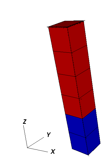
The following is an example XML <mesh> block, which will generate a vertical beam with two CellBlocks (one in red and one in blue in the following picture).
<Mesh>
  <InternalMesh name="mesh"
                elementTypes="C3D8"
                xCoords="0, 1"
                yCoords="0, 1"
                zCoords="0, 2, 6"
                nx="1"
                ny="1"
                nz="2, 4"
                cellBlockNames="cb1 cb2"/>
</Mesh>
namethe name of the mesh bodyelementTypesthe type of the elements that will be generated.xCoordList ofxcoordinates of the boundaries of theCellBlocksyCoordList ofycoordinates of the boundaries of theCellBlockszCoordList ofzcoordinates of the boundaries of theCellBlocksnxList containing the number of cells inxdirection within theCellBlocksnyList containing the number of cells inydirection within theCellBlocksnzList containing the number of cells inzdirection within theCellBlockscellBlockNamesList containing the names of theCellBlocks
Mesh Bias
The internal mesh generator is capable of producing meshes with element sizes that vary smoothly over space.
This is achieved by specifying xBias, yBias, and/or zBias fields.
(Note: if present, the length of these must match nx, ny, and nz, respectively, and each individual value must be in the range (-1, 1).)
For a given element block, the average element size will be
![dx_{average}[i] = \frac{xCoords[i+1]-xCoords[i]}{nx[i]},](../../../_images/math/8ed2f73f46dbb86ea3f6aa44f796cac76fd462a9.svg)
the element on the left-most side of the block will have size
![dx_{left}[i] = (1 + xBias[i]) \cdot dx_{average}[i],](../../../_images/math/dd786748bb7cbdccc7d2d755499814448e81e84a.svg)
and the element on the right-most side will have size
![dx_{right}[i] = (1 - xBias[i]) \cdot dx_{average}[i].](../../../_images/math/ffb38e8e0ffe2f6b36d4b1ec64c0656306d19a1f.svg)
The following are the two most common scenarios that occur while designing a mesh with bias:
- The size of the block and the element size on an adjacent region are known. Assuming that we are to the left of the target block, the appropriate bias would be:
![xBias[i] = 1 - \frac{nx[i] \cdot dx_{left}[i+1]}{xCoords[i+1]-xCoords[i]}](../../../_images/math/6145ed129d0b475c8c26f9e5e9ed23540fef9f86.svg)
- The bias of the block and the element size on an adjacent region are known. Again, assuming that we are to the left of the target block, the appropriate size for the block would be:
![xCoords[i+1]-xCoords[i] = \frac{nx[i] \cdot dx_{left}[i+1]}{1 - xBias[i]}](../../../_images/math/64704c4be027436b3233f008db40fe30fa7e1bfc.svg)
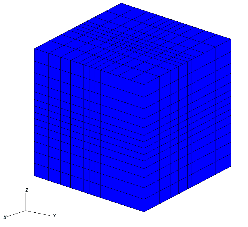
The following is an example of a mesh block along each dimension, and an image showing the corresponding mesh. Note that there is a core region of elements with zero bias, and that the transitions between element blocks are smooth.
  <Mesh>
    <InternalMesh
      name="mesh1"
      elementTypes="{ C3D8 }"
      xCoords="{ -10, -1, 0, 1, 10 }"
      yCoords="{ -10, -1, 0, 1, 10 }"
      zCoords="{ -10, -1, 0, 1, 10 }"
      nx="{ 4, 1, 1, 4 }"
      ny="{ 5, 1, 1, 5 }"
      nz="{ 6, 1, 1, 6 }"
      xBias="{ 0.555, 0, 0, -0.555 }"
      yBias="{ 0.444, 0, 0, -0.444 }"
      zBias="{ 0.333, 0, 0, -0.333 }"
      cellBlockNames="{ cb1 }"/>
  </Mesh>

  <Solvers>
    <SolidMechanics_LagrangianFEM
      name="lagsolve"
      strainTheory="1"
      cflFactor="0.25"
      discretization="FE1"
      targetRegions="{ Region2 }"
      />
  </Solvers>
Advanced Cell Block Specification
It’s possible to generate more complex CellBlock using the InternalMeshGenerator.
For instance, the staircase example is a model which is often used in GEOSX as an integrated
test. It defines CellBlocks in the three directions to generate a staircase-like model
with the following code.
<Mesh>
  <InternalMesh name="mesh1"
                elementTypes="{C3D8}"
                xCoords="{0, 5, 10}"
                yCoords="{0, 5, 10}"
                zCoords="{0, 2.5, 5, 7.5, 10}"
                nx="{5, 5}"
                ny="{5, 5}"
                nz="{3, 3, 3, 3}"
                cellBlockNames="{b00,b01,b02,b03,b04,b05,b06,b07,b08,b09,b10,b11,b12,b13,b14,b15}"/>
</Mesh>

<ElementRegions>
   <CellElementRegion name="Channel"
                  cellBlocks="{b08,b00,b01,b05,b06,b14,b15,b11}"
                  materialList="{fluid1, rock, relperm}"/>
   <CellElementRegion name="Barrier"
                  cellBlocks="{b04,b12,b13,b09,b10,b02,b03,b07}"
                  materialList="{}"/>
</ElementRegions>
Thus, the generated mesh will be :

Using an External Mesh
Supported Formats
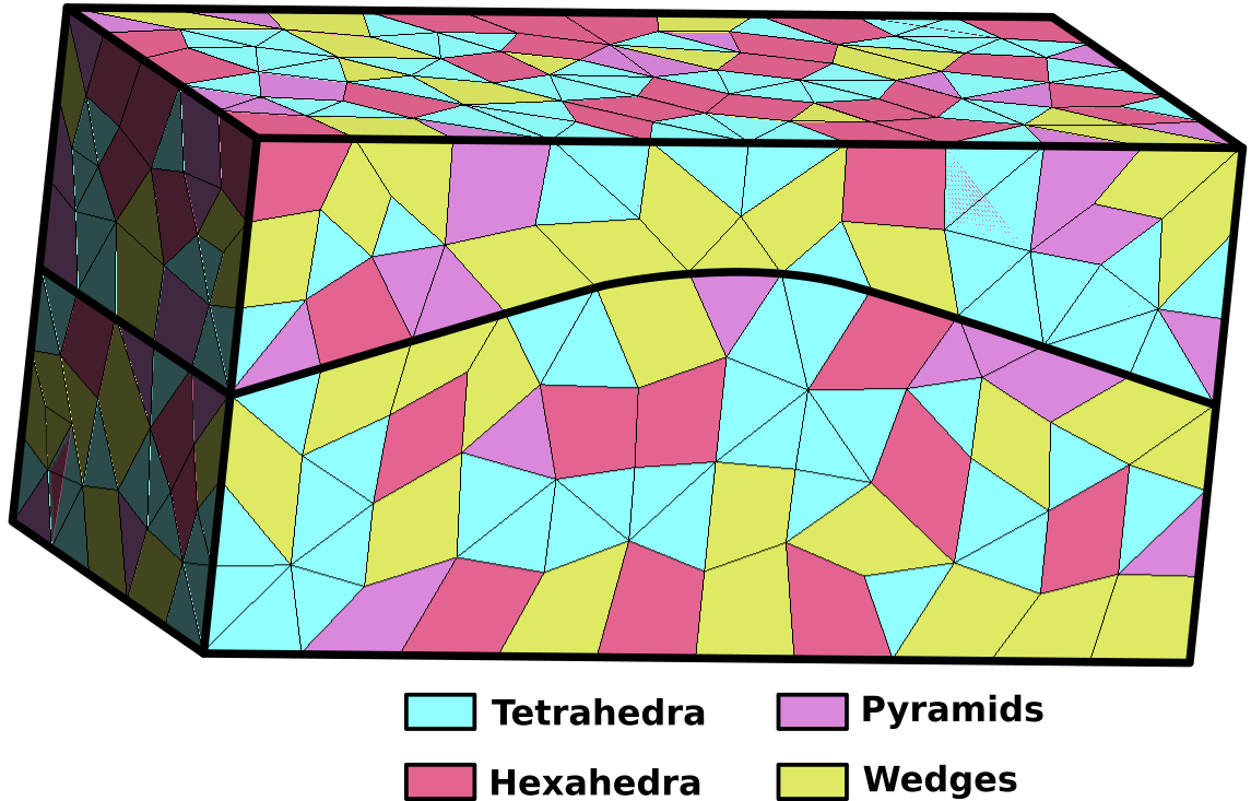
GEOSX provides features to run simulations on unstructured meshes. It uses VTK to read the external meshes and its API to write it into the GEOSX mesh data structure.
The supported mesh elements for volume elements consist of the following:
- 4-node tetrahedra,
- 5-node pyramids,
- 6-node wedges,
- 8-node hexahedra,
- n-gonal prisms (n = 7, …, 11).
The mesh can be divided in several regions.
These regions are intended to support different physics
or to define different constitutive properties.
We usually use the attribute field is usually considered to define the regions.
Importing the Mesh
Importing regions
Several blocks are involved to import an external mesh into GEOSX, defined in the XML input file.
These are the <Mesh> block and the <ElementRegions> block.
The mesh block has the following syntax:
<Mesh>
  <VTKMesh
    name="MyMeshName"
    file="/path/to/the/mesh/file.vtk"/>
</Mesh>
We advise users to use absolute path to the mesh file.
GEOSX uses ElementRegions to support different physics
or to define different constitutive properties.
An ElementRegion is defined as a set of CellBlocks.
A CellBlock is an ensemble of elements with the same element geometry.
In the example presented above, the mesh is is composed of two regions (Top and Bot).
Each region contains 3 CellBlocks.
The ElementRegions are defined as below :
<ElementRegions>
  <ElementRegion
    name="Top"
    cellBlocks="Top_hexahedra Top_wedges Top_tetrahedra"
    materialList="water rock"/>
  <ElementRegion
    name="Bot"
    cellBlocks="Bot_hexahedra Bot_wedges Bot_tetrahedra"
    materialList="water rock"/>
</ElementRegions>
You have to use the following syntax to declare your CellBlocks :
nameOfTheRegionWithinTheMesh_typeOfTheElement
The keywords for the element types are :
- hexahedra
- tetrahedra
- wedges
- pyramids
- pentagonalPrisms
- hexagonalPrisms
- heptagonalPrisms
- octagonalPrisms
- nonagonalPrisms
- decagonalPrisms
- hendecagonalPrisms
- polyhedra
An example of a vtk file with all the physical regions defined is used in Tutorial 3: Regions and Property Specifications.
Importing surfaces
Surfaces are imported through point sets in GEOSX. This feature is supported using only the vtk file format.
In the same way than the regions, the surfaces of interests can be defined using the `physical entity names`_.
The surfaces are automatically import in GEOSX if they exist in the vtk file.
Within GEOSX, the point set will have the same name than the one given in the file. This name can be used
again to impose boundary condition. For instance, if a surface is named “Bottom” and the user wants to
impose a Dirichlet boundary condition of 0 on it, it can be easily done using this syntax.
<FieldSpecification
  name="zconstraint"
  objectPath="nodeManager"
  fieldName="Velocity"
  component="2"
  scale="0.0"
  setNames="{ Bottom }"/>
The name of the surface of interest appears under the keyword setNames. Again, an example of a vtk file
with the surfaces fully defined is available within Tutorial 3: Regions and Property Specifications or CO2 Plume Evolution With Hysteresis Effect on Relative Permeability.